
How to Choose the Right Gear Drive Motor?

Choosing the right Gear Drive Motor begins with the load, not the catalogue cover. The motor must match torque, speed, duty cycle, shock loading, and installation space. A conveyor carrying wet aggregate needs a different solution from a quiet packaging line. Gear ratio matters. So does thermal capacity.

Industry forecasts show why this decision deserves care. Grand View Research estimates that the global gear motors market was worth several billion US dollars in 2023, with continued growth expected through the decade. MarketsandMarkets also identifies automation, material handling, and energy-efficient machinery as major demand drivers. These reports use different methods, so their figures should not be treated as identical facts. Still, the direction is clear: more equipment depends on compact, controllable, and reliable geared motion.

John Piotrowski, author of The Shaft Alignment Handbook, has often stressed a practical maintenance principle: “The goal of precision maintenance is to eliminate the root causes of failure.” That idea belongs in motor selection. A correctly sized Gear Drive Motor reduces overheating, backlash, lubrication problems, and premature bearing wear. IEC 60034 standards can help evaluate motor performance, while ISO 10816 guidance supports vibration monitoring after installation. Yet standards cannot replace field judgment. A clean specification sheet may hide frequent starts, side loads, or poor ventilation. That is where many choices fail. Measure the real load. Check the real environment. Then compare efficiency, service factor, noise, maintenance access, and total ownership cost—not purchase price alone.
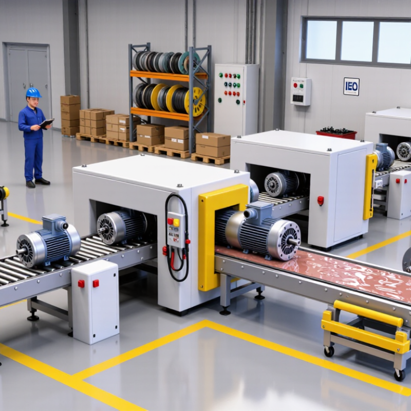
How to Choose the Right Gear Drive Motor?

Define the Application Requirements for a Gear Drive Motor

How to Choose the Right Gear Drive Motor?

Define the Application Requirements for a Gear Drive Motor

Choosing a gear drive motor starts with application requirements, not catalog size. Record output torque, speed, duty cycle, starts per hour, and load direction. A conveyor moving 80 kilograms may need modest running torque but much higher starting torque. Measure peak torque, not only average torque. It matters.

The International Energy Agency reports that electric motor systems consume nearly half of global electricity. The U.S. Department of Energy’s United States Industrial Motor Systems Market Opportunities Assessment estimated that motor systems used 69% of industrial electricity. These figures make efficiency, correct gearing, and controlled operation important engineering decisions. Select the gear ratio from the required output speed and torque. Then check motor efficiency, thermal limits, and service factor. A service factor cannot repair an incorrectly calculated load.

Consider the environment closely. Dust, moisture, washdown procedures, ambient temperature, mounting position, and available space can change the selection. In practical sizing, engineers should also verify backlash, shaft overhung load, braking needs, and gearbox life. A neat spreadsheet can still miss a short, severe shock load. That is where many selections become optimistic. Review the worst operating condition, not the average one. Use recognized motor and gearbox standards, and request test data when operating costs or safety margins matter.

Match Motor Torque, Speed, and Power to the Load

How to Choose the Right Gear Drive Motor?

A gear drive motor should match the load, not just the machine’s label. Start by measuring required torque at the output shaft. Include starting resistance, friction, product weight, and any sudden load changes. A conveyor may need much more torque during startup than during steady movement. I once saw a motor selected for running torque alone. It stalled repeatedly when the belt was fully loaded.

Speed matters just as much. Calculate the required output speed, then check the gear ratio and motor speed. A high ratio can increase torque, but it may reduce efficiency and create more heat. Allow for gearbox losses. Power connects torque and speed, so checking only one value can produce an unreliable selection. The motor should also handle the duty cycle, reversing frequency, ambient temperature, and expected service life. These details are easy to overlook.

Tips: Add a practical service margin, but avoid excessive oversizing. A motor that is too large may cost more and operate inefficiently. Check the manufacturer’s torque curve, thermal limits, and mounting conditions. Test the motor under the heaviest realistic load if possible. Measurements from the actual machine are more dependable than estimates. Recheck the choice after installation, because real friction and vibration may differ from early calculations.

Select the Appropriate Gearbox Type and Reduction Ratio

How to Choose the Right Gear Drive Motor?

Selecting the correct gearbox type and reduction ratio begins with the driven machine. Record the required output speed, torque, duty cycle, and installation position. A spur gearbox suits simple, low-cost applications with moderate loads. Helical gearing runs more quietly and handles continuous operation efficiently. Planetary designs provide high torque in a compact space, while worm gearboxes offer strong speed reduction and holding ability. However, worm systems can lose more energy through heat.

Calculate the reduction ratio by dividing motor speed by required output speed. For example, a 1,800 rpm motor producing 90 rpm needs a 20:1 ratio. Do not select the ratio from speed alone. The gearbox must also deliver enough output torque after efficiency losses. Check the starting load, acceleration time, and possible shock loads. A conveyor carrying uneven boxes may need more reserve than a smooth fan.

In field installations, I have seen motors fail because the selected ratio looked correct on paper. The actual load was higher during startup. Leave a practical safety margin, but avoid excessive oversizing. An oversized gearbox can increase cost, weight, and mechanical stress. Also check backlash, noise, heat dissipation, shaft alignment, and mounting space. I still verify calculations with real operating measurements, because assumptions can be wrong. Short tests under full load often reveal problems that specifications hide.

Evaluate Efficiency, Duty Cycle, Size, and Operating Conditions

How to Choose the Right Gear Drive Motor?

Efficiency should be measured at the actual load, not only from the nameplate. The International Energy Agency estimates that motor systems consume about 46% of global electricity and nearly 69% of industrial electricity. Small efficiency losses can therefore become expensive over long operating hours. Check motor efficiency, gearbox losses, and expected speed reduction together. A motor drawing 8 kW for 6,000 hours annually wastes more energy when poorly matched. Measure the load if possible.

Duty cycle changes the decision. A conveyor running continuously needs a different thermal rating than a gate moving twice daily. Review starting torque, peak loads, reversals, and daily operating hours. The U.S. Department of Energy links proper motor-system sizing with significant energy-saving opportunities in industrial facilities. Oversizing feels safe. It can still reduce efficiency and increase purchase cost.

Size and operating conditions also matter. Leave room for ventilation, but avoid unnecessary bulk. Dust, washdown water, heat, altitude, and corrosive air may require stronger protection. A compact motor installed beside a hot furnace may fail sooner than expected. That detail is easy to miss. I would record shaft loads, ambient temperature, mounting position, and maintenance access before choosing. Calculations are useful, but field conditions often expose their weaknesses. Recheck the selection after one production cycle.

How to Choose the Right Gear Drive Motor? - Evaluate Efficiency, Duty Cycle, Size, and Operating Conditions

Selection Dimension What to Evaluate Typical Reference Data Why It Matters Recommended Selection Approach
Required Output Torque Load torque, acceleration torque, friction, incline angle, and safety margin Torque: 0.5–500 N·m for many compact industrial gear motors
Safety factor: commonly 1.25–2.0, depending on shock loading
An undersized motor may overheat, stall, or experience premature gear and bearing wear. Calculate continuous and peak torque separately, then select a unit whose rated torque exceeds both requirements.
Output Speed Required shaft speed, speed range, starting speed, and allowable speed variation Common output speeds: approximately 5–300 rpm
Reduction ratios: often 3:1 to 300:1, depending on motor speed and gearbox design
Incorrect speed can reduce process quality, increase wear, or prevent the driven machine from operating correctly. Use the target speed under the actual load, not only the no-load motor speed. Consider an inverter when variable speed is required.
Gearbox Efficiency Gear type, reduction ratio, lubrication, operating temperature, and load level Typical ranges:
Helical: about 90–98%
Bevel-helical: about 90–97%
Worm: about 50–90%, strongly dependent on ratio and design
Lower efficiency increases input power, heat generation, and operating cost. Choose a high-efficiency helical or bevel-helical arrangement for continuous-duty applications; use worm gearing where compactness or self-locking behavior is important and efficiency is acceptable.
Motor Efficiency Motor technology, rated load, voltage, frequency, cooling, and control method Industrial induction motors: commonly about 80–95% at rated load
Efficiency generally decreases at very light load
Motor losses directly affect energy consumption and enclosure temperature. Compare the combined motor-and-gearbox efficiency at the expected operating point rather than comparing motor efficiency alone.
Duty Cycle Operating time, starts per hour, reversing frequency, load profile, and rest intervals Continuous duty: S1
Short-time duty: S2
Intermittent periodic duty: S3
A 40% duty cycle means approximately 40% operating time within each cycle
Thermal stress depends on average heating, not only the maximum rated power. Select a continuous-duty rating for uninterrupted operation. For intermittent systems, verify equivalent thermal load and starting capability.
Starting and Peak Load Breakaway torque, acceleration time, inertia, jam conditions, and braking requirements Starting torque may be several times the running torque, depending on motor type and controller. High starting demand can cause voltage drop, nuisance trips, overheating, or failure to accelerate. Check motor starting torque, gearbox peak torque, acceleration time, and controller current limit under the heaviest start condition.
Physical Size and Mounting Available envelope, shaft orientation, mounting position, shaft diameter, and flange or foot arrangement Gear motor dimensions vary widely with power, ratio, torque rating, and mounting configuration. A suitable torque rating is not useful if the motor cannot be installed or properly aligned. Confirm overall length, mounting-hole pattern, shaft overhang, service access, cable clearance, and allowable mounting orientation.
Operating Temperature Ambient temperature, enclosure heat, airflow, altitude, and thermal derating Many standard motor applications are designed around approximately −20°C to +40°C ambient conditions, subject to the product specification. Higher ambient temperature reduces the available thermal margin and may require derating. Apply the manufacturer’s derating data for high ambient temperature, high altitude, restricted ventilation, or frequent starts.
Ingress Protection Exposure to dust, water spray, washdown, humidity, and solid particles IP54: limited dust protection and protection against water splashes
IP65: dust-tight and protected against water jets
Insufficient sealing can lead to corrosion, insulation damage, bearing failure, and lubricant contamination. Select the IP rating according to the actual environment and washdown procedure; verify that cable glands and connectors provide equivalent protection.
Environmental Conditions Corrosive chemicals, explosive atmospheres, vibration, shock, outdoor exposure, and food-processing requirements Hazardous locations may require certified equipment for the specific gas, vapor, dust group, and temperature class. The correct electrical and mechanical rating prevents unsafe operation and premature deterioration. Define the environmental classification before selection. Do not use a standard motor in a hazardous area without the required certification.
Noise and Vibration Gear tooth design, bearing condition, alignment, mounting stiffness, and operating speed Helical gear arrangements are generally smoother and quieter than equivalent straight-tooth arrangements. Excessive noise or vibration may indicate resonance, misalignment, imbalance, or inadequate mounting. Specify noise limits where needed, use rigid alignment, and evaluate vibration under the actual load and speed range.
Power Supply and Control Voltage, phase, frequency, available current, variable-speed operation, braking, and feedback Common industrial supplies include single-phase or three-phase AC systems at 50 or 60 Hz, but actual voltage must match the installation. A mismatch can cause poor starting, overheating, incorrect speed, or controller faults. Confirm electrical compatibility, overload settings, acceleration ramps, braking method, and electromagnetic compatibility requirements.
Maintenance and Service Life Lubrication method, bearing life, seal replacement, inspection access, spare parts, and expected operating hours Gearbox life is influenced by load, speed, lubrication, temperature, contamination, and shock loading. A low initial price may lead to higher downtime and lifecycle cost if service access is difficult. Compare total cost of ownership, planned maintenance intervals, lubricant requirements, and replacement time.
Final Verification Rated torque, peak torque, output speed, duty, efficiency, temperature, IP rating, mounting, and compliance Every value should be checked at the intended operating point and worst-case condition. A complete specification prevents errors caused by evaluating motor power alone. Request a complete technical datasheet and verify the selection against the application’s load profile before purchase.

Note: The ranges shown are general engineering references. Actual performance depends on the motor, gearbox design, ratio, lubrication, load profile, installation, and environmental conditions.

Compare Reliability, Maintenance Needs, and Total Operating Cost

How to Choose the Right Gear Drive Motor?

Choosing a gear drive motor begins with its working conditions, not its purchase price. A motor that matches the load usually runs cooler and lasts longer. Compare rated torque, duty cycle, speed range, and shock-load capacity. In field inspections, excessive heat and unusual noise often reveal poor sizing. That matters. A rigid housing, sealed bearings, and effective lubrication can improve reliability in dusty production areas. Ask for test data, service limits, and documented operating temperatures. Avoid relying only on attractive performance claims.

Maintenance needs deserve equal attention. Check whether technicians can inspect oil, replace seals, and reach mounting bolts without removing nearby equipment. Sealed units may reduce routine work, but they still require temperature and vibration checks. I have seen small leaks become expensive failures because inspections were delayed. Small faults grow. However, maintenance intervals listed in manuals may assume clean conditions and steady loads. Your plant may be harsher.

Total operating cost includes energy, lubricant, labor, spare parts, and unplanned downtime. Record the purchase price, then estimate costs across the motor’s expected service life. A highly efficient motor can reduce electricity use during long operating hours. A cheaper unit may consume more power and require frequent repairs. Real costs hide. Use actual production data when possible, and include lost output in the calculation. Leave room for uncertainty; operating conditions rarely remain perfect.

How to Choose the Right Gear Drive Motor?

Comparison of typical non-branded industrial benchmarks for service life, annual maintenance effort, and 10-year operating cost. Lower maintenance hours and cost index are better.

Values represent common engineering benchmark midpoints: service life depends on load, lubrication, alignment, duty cycle, and operating environment. The operating cost index uses the helical motor as the reference value of 100 and combines typical energy, lubrication, inspection, and replacement-related costs over ten years.

AVADA IT

Fusce ut ipsum tincidunt, porta nisl sollicitudin, vulputate nunc. Cras commodo leo ac nunc convallis ets efficitur.

RECENT TWEETS

CONTACT US

  • 12345 North Main Street,
    New York, NY 555555

  • 1.800.555.6789

  • sale@vibrotools.com

Go to Top