Why Is a Regenerative Thermal Oxidizer Used in Industrial Emissions Control?
A Regenerative Thermal Oxidizer (RTO) is used to reduce volatile organic compounds and other combustible pollutants in industrial exhaust. It draws in contaminated air, heats it in a combustion chamber, and uses ceramic media to recover much of that heat. Picture warm exhaust passing through honeycomb-like ceramic beds before cleaner gas leaves the stack. The result can be effective emissions control with lower fuel demand than a system that discards its heat.
Why choose an RTO? Many facilities produce large, changing exhaust flows from coating lines, printing operations, or chemical processes. An RTO can handle these streams when the system is properly designed and operated. Performance depends on details: inlet concentration, airflow, temperature, residence time, and maintenance. A blocked ceramic bed or poorly balanced valve can undermine efficiency. The equipment is powerful, but not self-managing.
One sourcing point matters: I cannot verify a named expert’s exact quotation from the material provided, so I will not invent one. A reliable introduction should use a documented statement from a qualified emissions-control engineer, with the source identified. That extra check may feel slow. It protects readers from a polished but unsupported claim, and it sets a sound basis for exploring how RTOs work, where they fit, and what operators should evaluate.
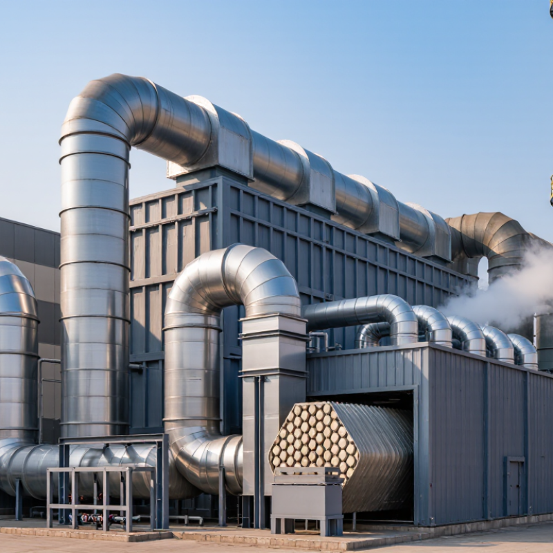
Industrial Emissions That Require Treatment
Industrial exhaust often carries volatile organic compounds from solvent cleaning, paint drying, printing, and resin production. These vapors may create strong odors and contribute to ground-level ozone formation. A regenerative thermal oxidizer can treat suitable streams by heating pollutants until they oxidize, then recovering much of the heat in ceramic media. The exhaust does not simply disappear. Its composition and flow rate matter.
Some processes release emissions in short bursts. A coating line may produce a solvent-rich plume during drying, while a mixing vessel releases vapors only when opened. RTO systems are often considered when these exhaust streams are consistent enough to collect and control. They may also be used for certain odor-causing organic compounds. But they are not a universal answer. Dust, corrosive gases, moisture, or changing pollutant levels can affect performance and may require pretreatment or another control method.
The details can be unglamorous: a damp duct, a clogged filter, or a sudden production change can alter the incoming stream. Operators need reliable measurements of temperature, flow, and pollutant concentration. A design based on average conditions alone can miss real operating peaks. That is an easy assumption to make, and worth questioning.
How a Regenerative Thermal Oxidizer Destroys Pollutants
A regenerative thermal oxidizer destroys pollutants by heating contaminated exhaust until volatile organic compounds and other combustible pollutants react with oxygen. In the combustion chamber, temperatures commonly reach roughly 760–820°C, depending on the process and pollutant mix. The hot gas then passes through ceramic media, which stores heat. This matters: preheated incoming exhaust needs less supplemental fuel. The U.S. Environmental Protection Agency’s Air Pollution Control Cost Manual describes regenerative systems with typical heat-recovery efficiencies around 90–95% and pollutant destruction efficiencies often above 95%. Actual results depend on operating conditions and system design.
The ceramic beds alternate roles. One bed absorbs heat from treated gas, while another releases stored heat to warm incoming exhaust; valves switch the flow periodically. A small amount of untreated gas can remain in the system during each switch, so purge arrangements and maintenance affect performance. Small details matter. Operators monitor chamber temperature, flow, pressure, and outlet pollutant levels to spot problems such as fouling or uneven flow. EPA guidance reports that well-designed thermal oxidizers can achieve high destruction efficiency, but a published figure is not a guarantee for every plant. Real exhaust varies. That variability deserves more attention than a single efficiency number.
Why Is a Regenerative Thermal Oxidizer Used in Industrial Emissions Control? - How a Regenerative Thermal Oxidizer Destroys Pollutants | Operating Dimension | Typical Range or Feature | Role in Emissions Control |
| Oxidation temperature | Commonly about 760–1,000°C (1,400–1,832°F), depending on the pollutant and process conditions | Provides the heat needed to oxidize many volatile organic compounds (VOCs) into carbon dioxide and water vapor. |
| Gas residence time | Often approximately 0.5–1.0 second in the oxidation chamber; actual design varies | Allows the heated gas to remain in the reaction zone long enough for effective oxidation under the specified operating conditions. |
| Heat recovery | Ceramic media commonly recovers roughly 90–97% of heat, depending on system design and operation | Transfers heat from treated exhaust to incoming process gas, reducing the supplemental fuel needed to maintain operating temperature. |
| VOC destruction efficiency | Many systems are designed for at least 95% destruction; performance depends on inlet composition, temperature, residence time, and maintenance | Indicates the proportion of targeted pollutants chemically converted in the oxidizer; site-specific testing is needed to confirm performance. |
| Regenerative heat exchange | Usually uses two or more ceramic-filled beds with alternating flow direction | One bed absorbs heat from treated gas while another preheats incoming gas; valves periodically reverse the flow. |
| Typical application | Large, relatively steady exhaust flows containing combustible VOCs at suitable concentrations | Well suited to processes such as coating, printing, and chemical manufacturing, subject to gas composition and safety assessment. |
| Important operating consideration | Inlet flow, pollutant concentration, contaminants, and system pressure drop require monitoring | Stable operation helps maintain treatment performance and identify issues such as fouling, excessive pressure drop, or unsuitable feed conditions. |
Note: Values are representative industry ranges, not guaranteed performance specifications. Actual operating limits and results depend on the process, equipment design, and applicable permit requirements.
How Ceramic Beds Recover Heat and Reduce Fuel Demand
A regenerative thermal oxidizer (RTO) destroys volatile organic compounds by heating contaminated process air. Its ceramic beds help limit the fuel needed to maintain operating temperature. Hot, treated gas passes through one bed, warming the ceramic blocks. A valve then redirects incoming exhaust through that stored heat. The warmed air needs less supplemental fuel. Heat moves in cycles. It is a practical exchange, though not a perfect one.
The U.S. Environmental Protection Agency’s Regenerative Incinerator fact sheet reports typical thermal energy recovery of about 85–95% and VOC destruction efficiencies of about 95–99%. These are reference ranges, not guarantees for every installation. Actual results depend on inlet concentration, airflow, operating temperature, and how well valves seal. On a cold start, or when exhaust flow changes sharply, burners may need to supply more heat. Ceramic beds also need inspection; dust buildup can restrict airflow and weaken heat transfer.
Tips: Track fuel use alongside inlet and outlet temperatures, not as a standalone number. Check pressure drop across each ceramic bed for gradual increases. Keep a simple log of startup conditions; small shifts can reveal fouling or leaking valves. Measurements matter. A little uncertainty remains: site-specific testing is the best way to confirm savings.
Industries and Emissions Suited to RTO Treatment
Regenerative thermal oxidizers suit exhaust streams containing volatile organic compounds from printing, coating, chemical processing, and pharmaceutical production. These operations can release solvent vapors during routine tasks, such as drying a freshly coated metal part. RTOs heat contaminated air in a combustion chamber, then capture heat in ceramic media for reuse. That heat recovery makes them most attractive when emissions flow steadily and contain enough combustible material to support treatment.
The U.S. Environmental Protection Agency’s Air Pollution Control Cost Manual reports that thermal oxidizers can achieve VOC destruction efficiencies around 98% or higher under appropriate operating conditions. Its technical guidance also describes regenerative systems as recovering much of the heat from treated gas, reducing fuel demand compared with less heat-efficient designs. Details matter. A dilute, intermittent exhaust stream may not deliver the same economics as a stable production line. Operators must also assess airflow, VOC concentration, moisture, and compounds that could foul the ceramic beds. I would not treat the headline efficiency as a guarantee; actual performance depends on design, monitoring, and maintenance. Sources: U.S. EPA, Air Pollution Control Cost Manual, Section 3, Chapter 2; EPA, VOC Control Techniques Guideline.
Why Use a Regenerative Thermal Oxidizer in Industrial Emissions Control?
RTOs are commonly used to treat exhaust containing volatile organic compounds (VOCs) from printing, coating, chemical processing, and similar operations. The chart shows typical performance ranges; actual results depend on system design and operating conditions.
RTOs destroy organic pollutants by heating exhaust in an oxidation chamber, while ceramic heat-exchange media recover heat from treated gas. They are not designed to remove every pollutant, such as particulate matter or metals.
Operational Factors That Shape RTO Performance
Operational Factors That Shape RTO Performance
A regenerative thermal oxidizer’s performance depends on more than its combustion chamber temperature. The U.S. Environmental Protection Agency’s “Regenerative Incinerator” fact sheet reports typical organic-compound destruction efficiencies of 95–99%, with heat-recovery efficiencies commonly around 85–95%. These figures describe operating conditions, not a guarantee for every exhaust stream. Flow rate, contaminant concentration, and changes in production can all affect results.
Temperature matters. So does residence time. If exhaust flow rises unexpectedly, gases may pass through the oxidation zone too quickly. Poorly balanced ceramic beds can also reduce heat recovery, increasing fuel demand. Operators therefore monitor chamber temperatures, pressure drop, and inlet concentrations, while checking for leaks or fouling. A pressure reading that slowly climbs may point to deposits restricting airflow. Small clues count.
The EPA figures are useful benchmarks, but real facilities vary. Moisture, particulate loading, and intermittent processes may complicate performance, and the ideal control settings can shift during a production day. It is tempting to treat high heat recovery as the whole story. It isn’t. A careful performance review compares operating data with actual exhaust conditions; otherwise, a neat efficiency number may hide uneven treatment across changing loads.