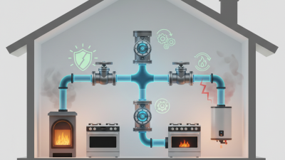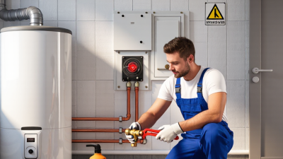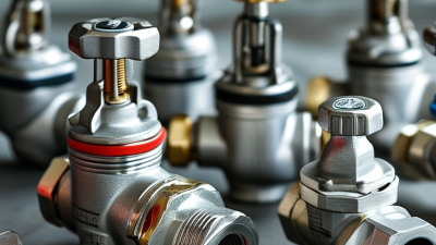
Gas valve installation is a safety-critical task that deserves more than a quick product comparison. For global buyers, the valve must match the gas type, pressure range, pipe material, and operating environment. A model suitable for a residential kitchen may fail in a commercial boiler room. Small mismatches can create leaks, unstable combustion, or costly downtime.
Reliable installation starts with verified technical data and qualified professionals. Buyers should review inlet and outlet sizes, flow direction, sealing materials, temperature limits, and pressure ratings before purchase. The installation area should remain accessible for inspection and emergency shutoff. Good technicians check pipe alignment, remove debris, apply compatible sealant, and avoid forcing threaded connections. They also perform leak and pressure tests using approved methods, never relying on smell alone. Keep records.
Global projects require careful communication. Product certificates, test reports, user manuals, and traceability documents should be available in a usable language. Local fuel standards and building requirements may differ, so a regional engineer should confirm the final arrangement. An experienced supplier can explain these differences, but buyers should still verify every claim independently. A checklist helps, yet it can miss site conditions, rushed work, or an unsuitable adapter. That is worth admitting. This guide explores seven practical gas valve installation tips, helping international buyers reduce avoidable errors and select equipment with greater confidence. Safety remains the real measure of value.
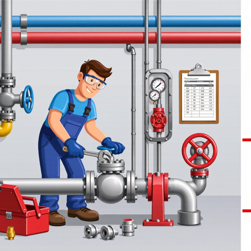
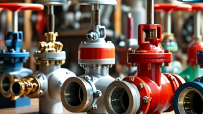
Choosing a gas valve starts with the application, not the catalog photo. Ball valves suit quick isolation, while globe valves support controlled flow. Check the gas composition, moisture level, and expected flow rate before selecting either type. Small differences matter.
Review pressure and temperature ratings together. A valve rated for high pressure may not suit cold service or rapid temperature changes. Match the connection type to the pipeline, such as threaded, flanged, or welded ends. Confirm the sealing material against the gas and operating temperature. Compatibility prevents leakage and premature failure. It sounds obvious.
Actuator selection also affects safety and maintenance. Manual valves work well at accessible points, while powered valves need suitable power, signal, and emergency positioning. Specify whether the valve should fail open or fail closed. Local codes and site rules must guide that decision. Requirements differ across markets, so documents need careful checking.
Ask for material certificates, pressure-test records, installation instructions, and traceable batch information.
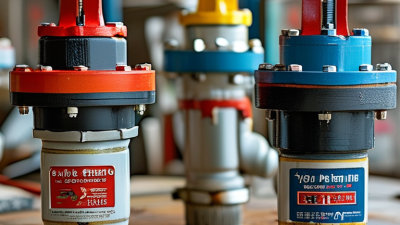
Inspect threads, flange faces, and protective caps before installation. I have seen damaged threads create problems that looked like valve defects. Do not force alignment with pipework. Support heavy actuators separately, then test shutoff performance under controlled conditions. Recheck the installation after initial operation; real systems often reveal assumptions that drawings miss.
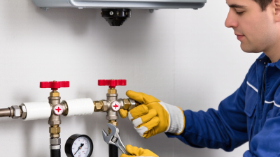
Gas valve performance begins with the site, not the catalog. Tip 1: record inlet pressure, temperature, gas density, and flow demand. Natural gas, LPG, and hydrogen blends require different seals and materials. Tip 2: inspect ventilation, drainage, corrosion, vibration, and maintenance access. A valve hidden behind equipment is difficult to isolate safely. Tip 3: confirm flow direction and connection dimensions before delivery. Small errors can delay commissioning.
Tip 4: match the valve to recognized standards, such as EN 161 or ISO 23550, where applicable. Local fuel-gas codes and authority requirements still control the final installation.
Tip 5: verify pressure ratings, shutoff performance, and electrical enclosure protection. The IEA’s Global Methane Tracker 2024 estimated over 120 million tonnes of methane emissions from fossil-fuel operations in 2023. Reliable shutoff and leak control matter. They also reduce waste.
Tip 6: check compatibility with the actual gas composition, including sulfur compounds, condensate, and hydrogen content. Ask for material certificates and temperature limits.
Tip 7: test every joint with an approved leak-detection method after installation. Never use a flame. Confirm emergency isolation access and label the valve clearly.
A checklist helps, but it can still miss changing site conditions. Recheck after pressure testing, thermal cycling, or nearby construction.
7 Gas Valve Installation Tips for Global Buyers
Preparing Tools, Seals, and Connection Points Before Installation
Prepare a calibrated torque wrench, pipe cutter, deburring tool, leak-detection fluid, and pressure gauge. Tip one: inspect every tool before work begins. Tip two: confirm the valve material, pressure rating, temperature range, and gas compatibility. These details should match the project specification and local code.
Tip three: clean connection points thoroughly. Remove dust, metal chips, oil, and old sealant from threads or flanges. Tip four: choose seals that match the gas, pressure, and temperature. Never assume a familiar gasket is suitable. Tip five: inspect threads, flange faces, and pipe alignment under bright light. Cross-threading often begins with poor alignment. Tip six: tighten gradually and use the manufacturer’s specified torque. Excessive force can distort seals or damage threads. This mistake is still common.
The U.S. Department of Energy reports that compressed-air leaks can waste 20–30% of system output. Gas installations require even stricter attention because leakage can create safety hazards. Tip seven: pressure-test the completed joint with approved procedures before commissioning. Use calibrated instruments and record the test pressure, duration, and result. ISO 5208 provides recognized valve leakage-testing methods, while applicable national codes may require additional checks. A practical lesson is simple: preparation takes minutes, but correcting a damaged seal can take hours. The checklist will not catch everything. Recheck it at the connection point.
7 Gas Valve Installation Tips for Global Buyers
Correct flow direction begins with the valve body arrow. It must match the gas movement shown on the piping drawing. A reversed valve may restrict flow, damage internal parts, or prevent emergency shutoff. Confirm the arrow before removing protective caps. Then compare the valve tag, line number, and gas service. Small details matter.
Alignment is not cosmetic. Pipe flanges should meet naturally, without pulling them together with bolts. Use temporary supports during installation, and keep the valve free from twisting loads. Tighten bolts in a cross pattern with a calibrated torque wrench. Do not use the valve body as a lever. It is a common shortcut. It is also a poor one. NFPA 54 and EN 1775 support controlled installation practices for fuel-gas systems, while ISO 5208 defines leakage-rate testing classifications for industrial valves. Follow the applicable local requirements.
A pressure test should verify the complete joint, not only the valve shell. Record test pressure, duration, temperature, and observed leakage. The IEA’s Global Methane Tracker 2024 estimated about 120 million tonnes of methane emissions from fossil-fuel operations in 2023. It also reported that roughly 40% could be avoided without increasing overall costs. Correct alignment cannot solve every leak, but it removes one preventable failure path. Inspectors should check valve position, flange gaps, support condition, and access for future maintenance. The installation may look correct and still need adjustment.
Installing a gas valve with the correct flow direction and alignment helps support safe, reliable, and maintainable operation. Use this seven-point checklist during installation and commissioning.
Testing and documenting a gas valve installation requires more than confirming that the handle turns. Tighten fittings to the specified torque, then perform a pressure test with calibrated equipment. API 598 provides defined test pressures and holding times for industrial valves. Record the medium, pressure, duration, gauge identification, and final result. Small details matter.
Tips: Inspect threads, seals, flanges, supports, and valve orientation before testing. Use a leak-detection solution around every joint, even when the pressure reading remains stable. Check the actuator’s full travel and confirm the fail-safe position. Photograph the valve tag, connections, gauge, and surrounding pipework. Keep the test certificate with the installation drawings and maintenance file.
NFPA 54 emphasizes approved materials, safe installation, inspection, and testing for fuel-gas systems. The International Energy Agency estimated about 120 million tonnes of methane emissions from fossil-fuel operations in 2023. A valve leak may be smaller, but poor records make repeated leaks harder to find. Do not trust one successful test. Temperature changes can alter readings, and a hidden gasket defect may appear later. Review the pressure trend, not only the final number. A perfect form can still hide a weak inspection. That deserves reflection.
© Copyright 2025 | LittleFirefighter.com | All Rights Reserved | 1EZ Creative: Orange County Web Design

Fusce ut ipsum tincidunt, porta nisl sollicitudin, vulputate nunc. Cras commodo leo ac nunc convallis ets efficitur.

12345 North Main Street,
New York, NY 555555
1.800.555.6789
sale@vibrotools.com